I have for awhile been wanting to be able to figure out how much power my meter was using daily, without reading the meter at the same time everyday, I also want to be able to graph my power usage.
While I haven’t completely solved the issue with an ip67 box, I have proven the concept. I have been doing a lot of research on power meters on your house, how they work, and how they calculate the kw/h consumtion of your house, through all of this I learned that there are meters that broadcast there signal, this can be intercepted, I knew that mine didn’t have that because the meter reader still comes to check the meter, plus I live in the country. The next type of meter was a meter that had a flashing LED that flashed whenever a kw/h was used, that could have been useful, except for the fact that my meter didn’t have that :-(. The last type I found was a meter that did infrared pulses for every watt hour, this was my last hope, before I had to breakout the clamp!
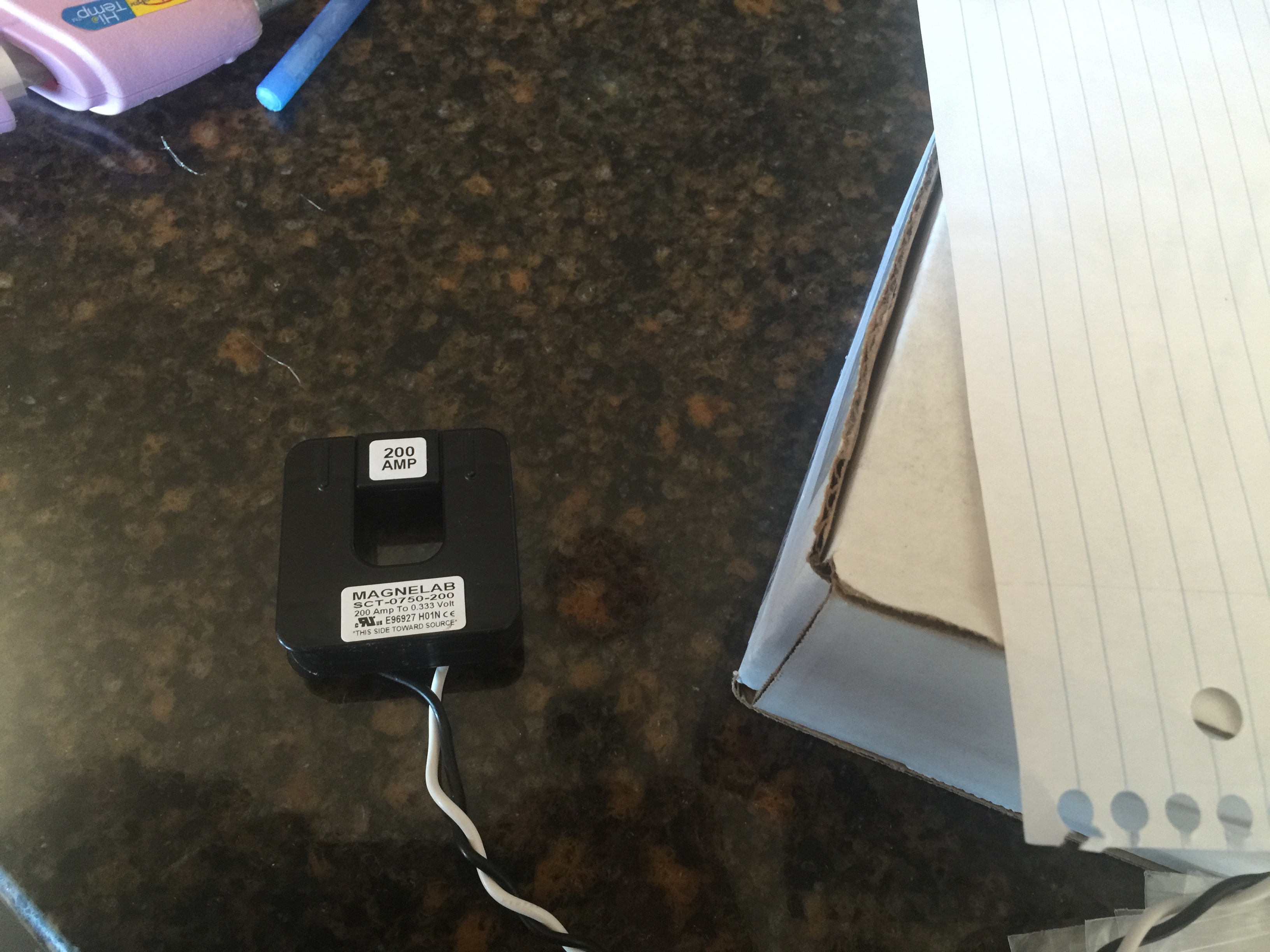
I really didn’t want to open my breaker boxes and clamp these on the feeds. Plus the circuit for that is complicated.
So while I was on the road to Des Moines earlier this weekend, I had my wife snap a shot of the top of the meter… And there is was…
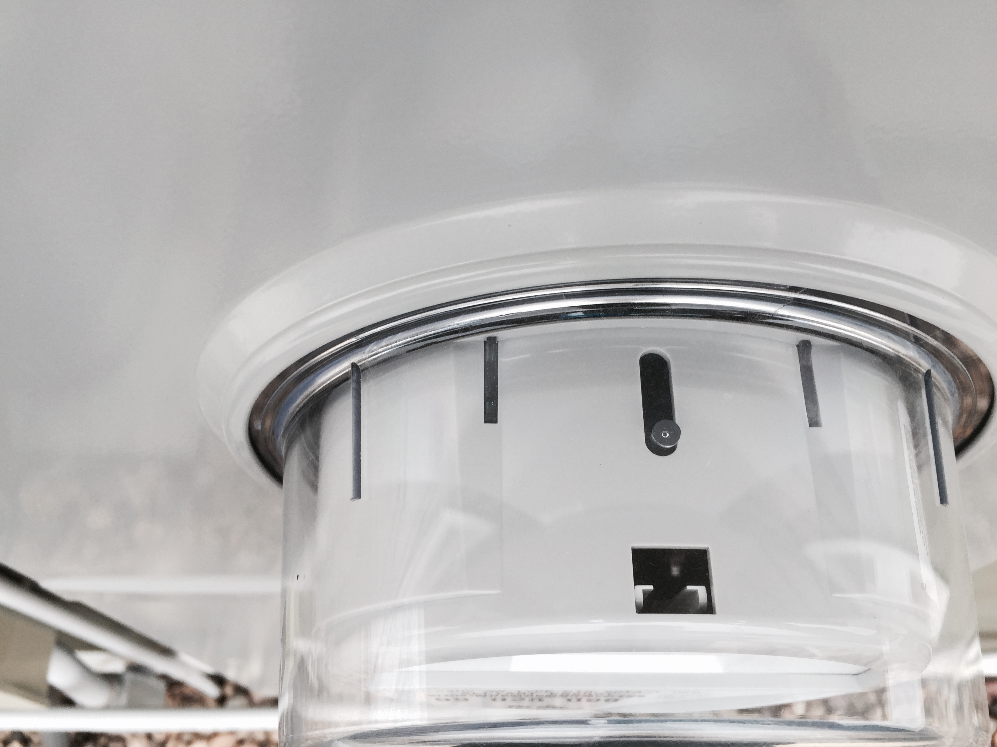
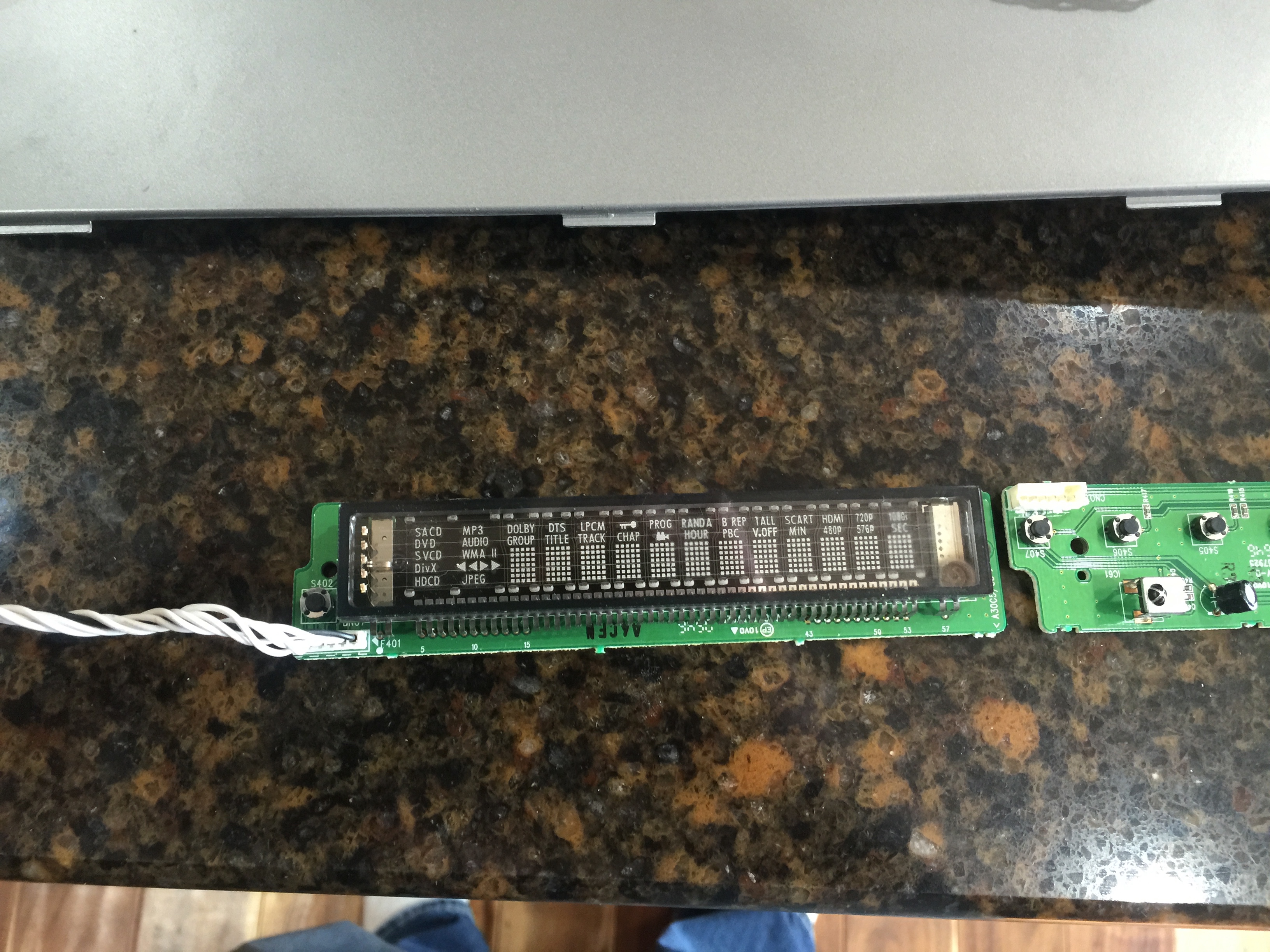
That little circuit had to be the IR transmitter. But what was the center channel??? While in Des Moines I took a look at my sisters meter as well (That’s right I am sure I am a super creeper).. Surprisingly her meter was the same as mine, I had guessed that she would probably have the wireless kind, since she lives in a more heavily populated area. Not a single document I read told me what the center channel was, then I got to thinking why do I care what the center channel is?!?!? All I cared about was the pulses, center channel didn’t matter. So when I got home on Saturday I went to work. First hack into a broken DVD player and grab a infrared receiver.
Hello Mr Harmon Kardon DVD player:
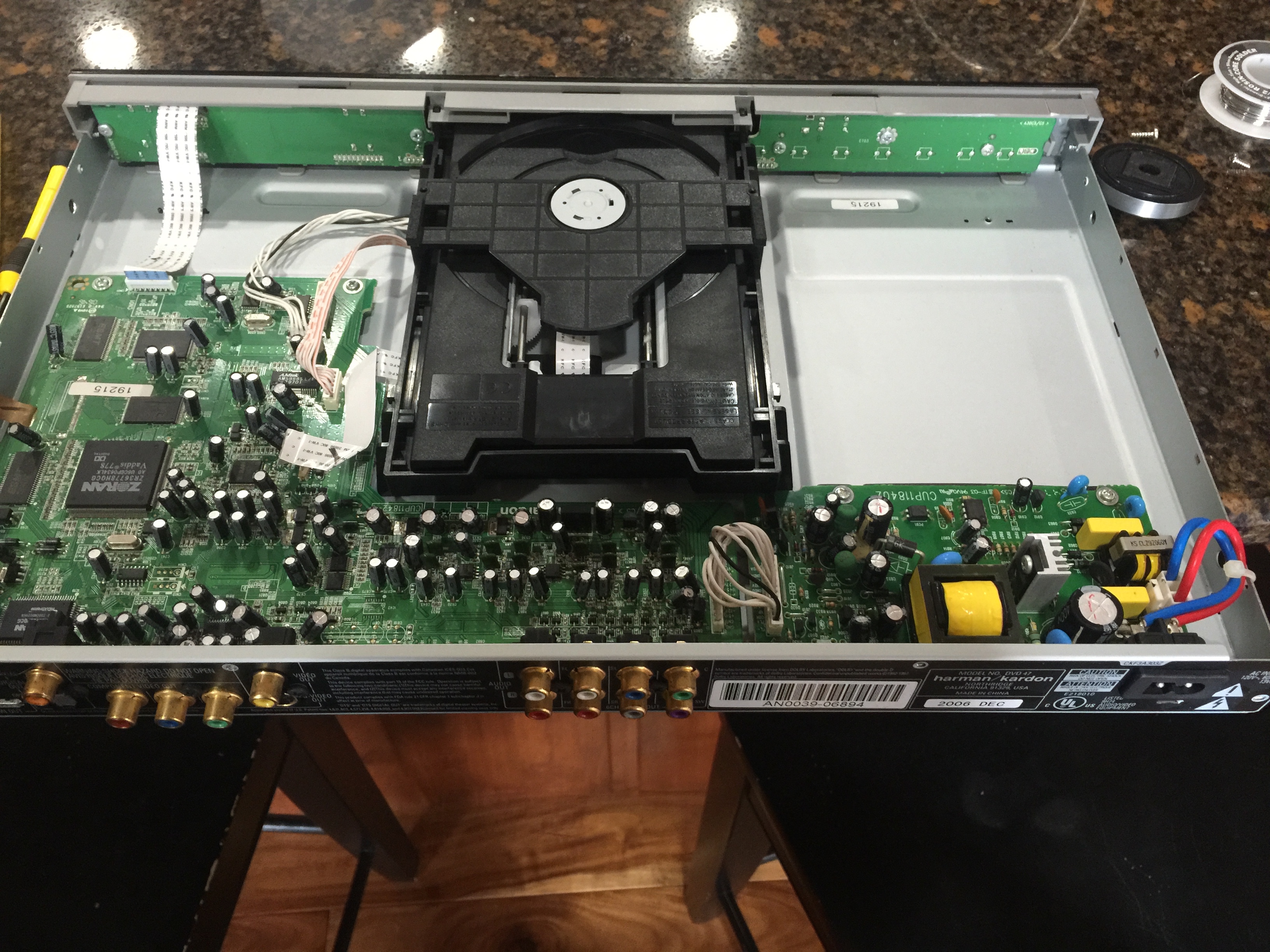
Look at what you have for me (IC61):

This… This is not relevant, but it looks interesting so I am pulling it too while I am in here.
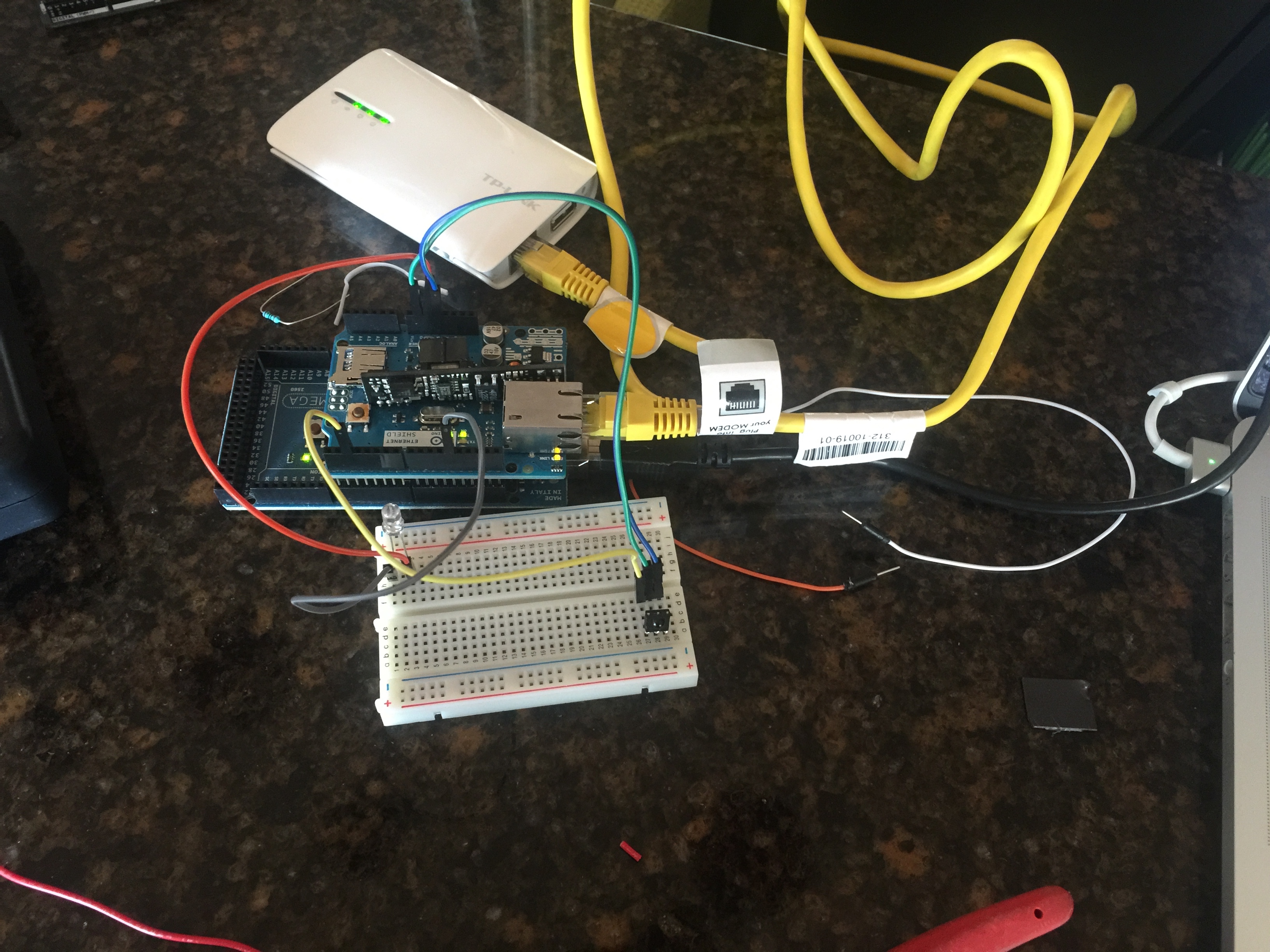
ok so now I had my IR, I could NOT find any data on the listed serial number.. Bummer, but it was 3 wire, So what was I to do?? How about make an educated guess, I know the TSOP is a very popular IR, so I just assumed that the wires were the same. (http://www.vishay.com/docs/82459/tsop48.pdf) and I was right, so I wired it to an Arduino, with an LED for testing.
Good things happened! (The Frozen Music is free too)
I then added the Ethernet shield.
Then tragedy struck… I was using an interrupt to watch for IR, but the shield interfered with the interrupt. So I switched to a poller, and that seemed to work well (code to follow).
So then I needed to case it, The only Ethernet shield that I had only supported POE, this was cool, yet bad because it wouldn’t fit in the case… Oh well, proof of concept. I needed to hot glue the light in.
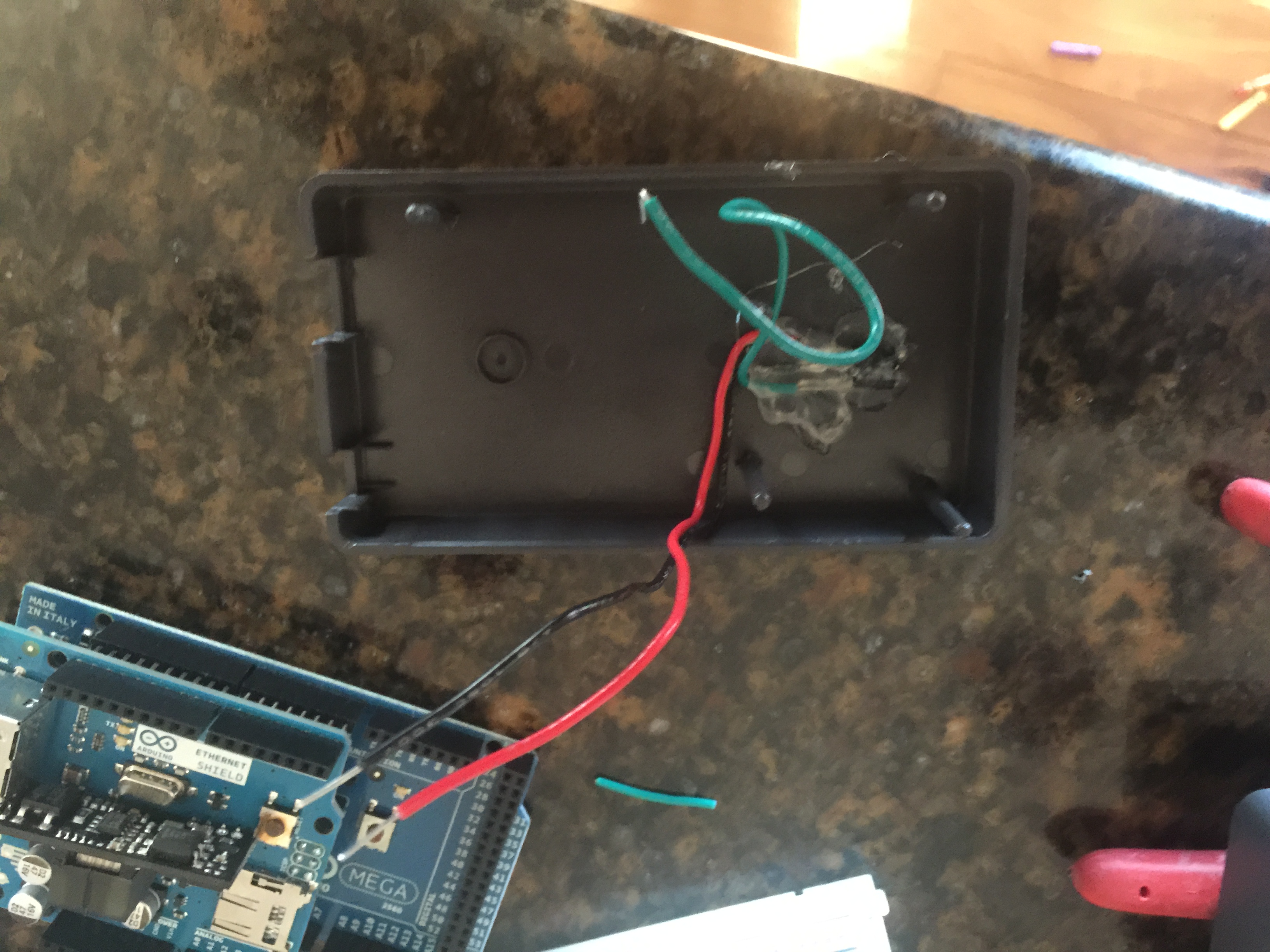
Mad hot glue skills I know.
I then discovered that light seemed to affect the IR sensor. So I needed to block all right from the receiver. I had my wife do a little sewing on a piece of material that I could pull around the meter. The result looks like this:
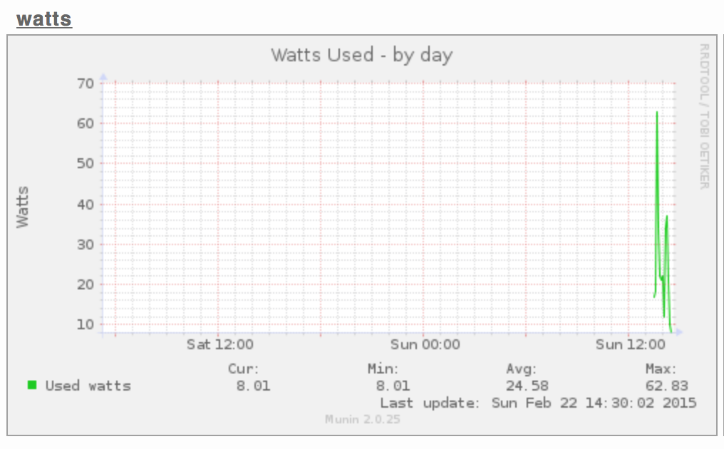
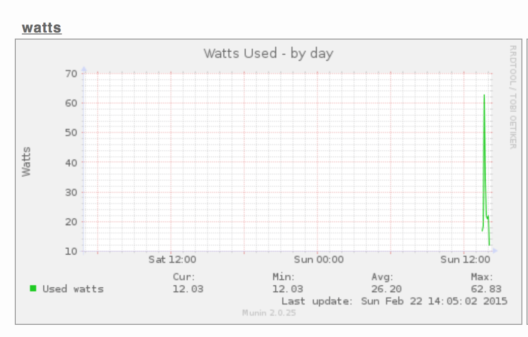
Lastly I needed to graph the data…. Munin seems perfect for this…
I ran the dryer to show it spike up…
Here is showing it in live log mode..
Good project with great results!!!
Have Fun!
John “Make Your House Smarter” Hass
The Graph after writing this post