So curiosity got the better of me and I wandered since Arduino is open source, if it would be possible to build an arduino without any pull-up resistors, fancy oscillators, simply a chip and a breadboard. Oh and I wanted to make sure it was cheap!
TL;DR – I did it.
The process did take awhile I ran into multiple challenges along the way. Keep in mind I didn’t have a chip programmer, so I needed to use an arduino to actually burn the boot loader code, and since I didn’t have an uno, I had to actually breadboard out the burn. In the end I am able to use a cheap FTDI adapter to program my “Arduino”
The crazy plane
1. Atmega328 ( I screwed up and got the 328-PU, so I had a little more heartache) This one is nice, because it’s already flashed with Arduino: http://bit.ly/1FbU1g3 but to really cut your teeth get the PU model, and save a dollar http://bit.ly/1wi3HBt
2. a breadboard w/ wires. http://amzn.to/1tzB7gc
3. A couple of LED’s http://amzn.to/103YUrz
4. If you don’t have an uno to use the FTDI, get a FTDI adapter http://bit.ly/1oehCri
5. 0.1uF Capacitor http://bit.ly/1zf4uqL
Total Price:
Atmega: 3.55
Breadboard: 9.69
LED: 4.57
FTDI: 12.71
0.1uF: .25
For a total of: 30.77
Not a totally stellar price, by any means, but look around for a cheaper stuff you will find it. Also in the end you can actually incorporate an arduino into your final soldered circuit board, only adding 3.55, Very nice.
The plan:
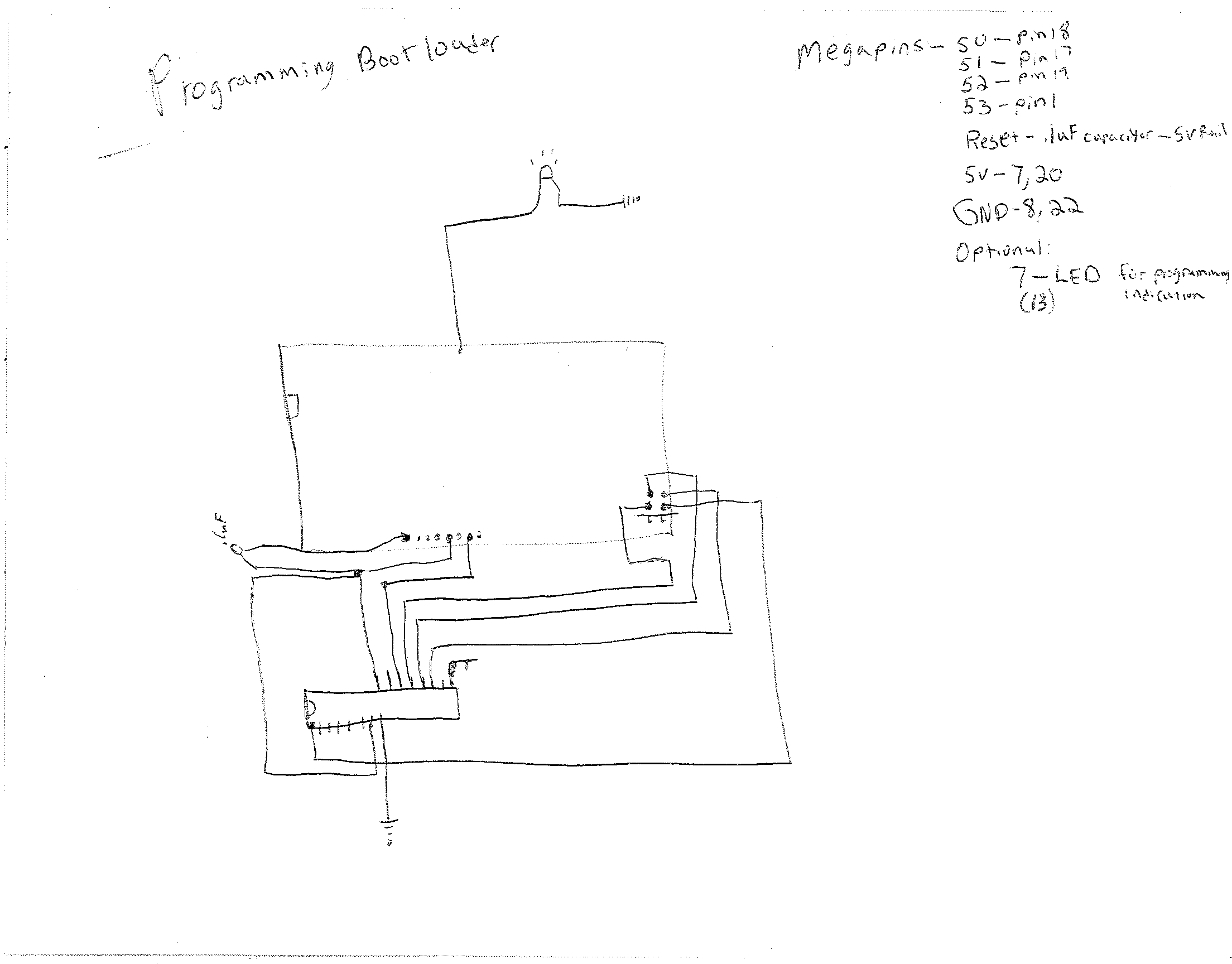
This is the programmer.
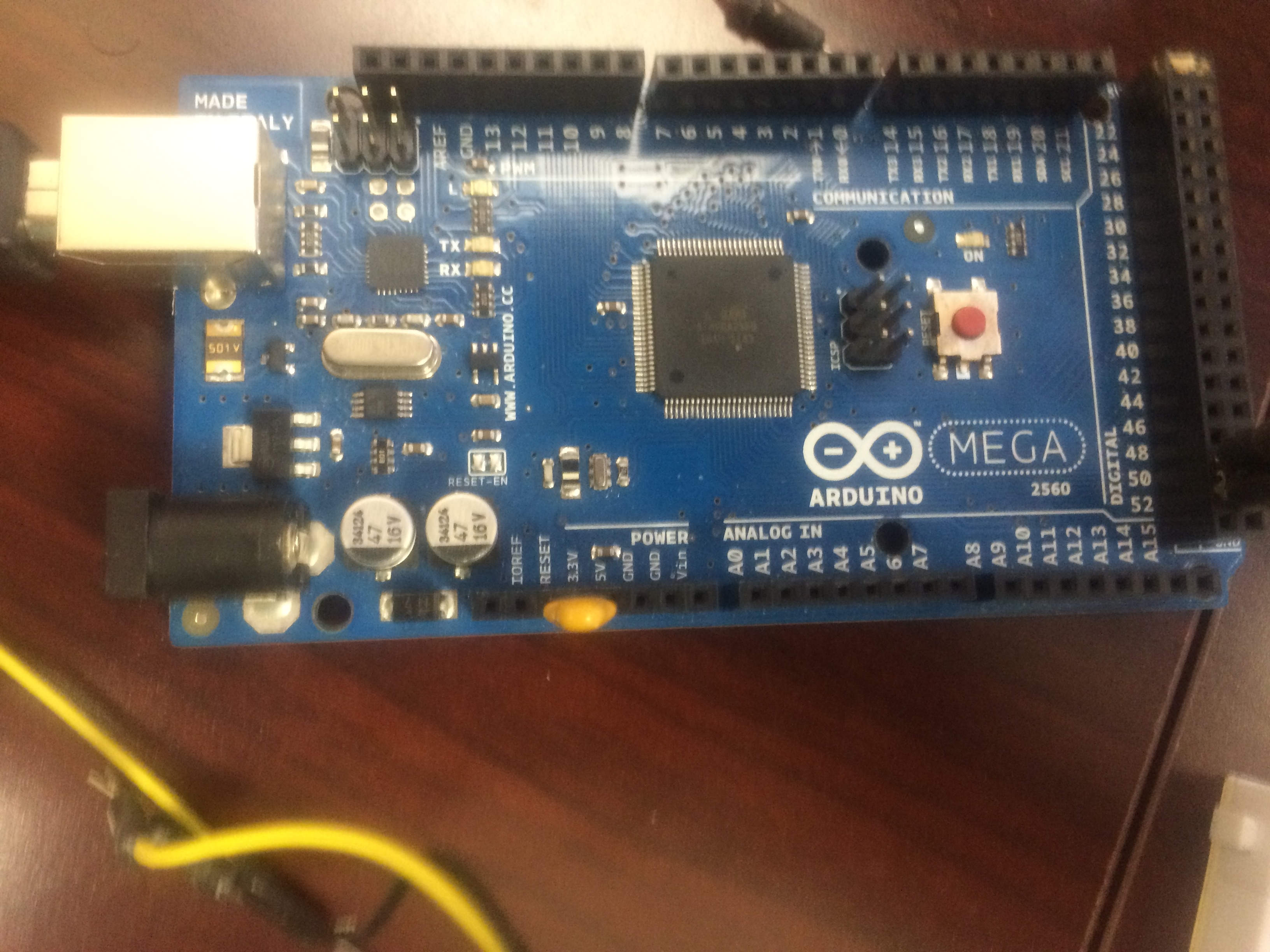
So I was using the Arduino Mega 2560 to program:
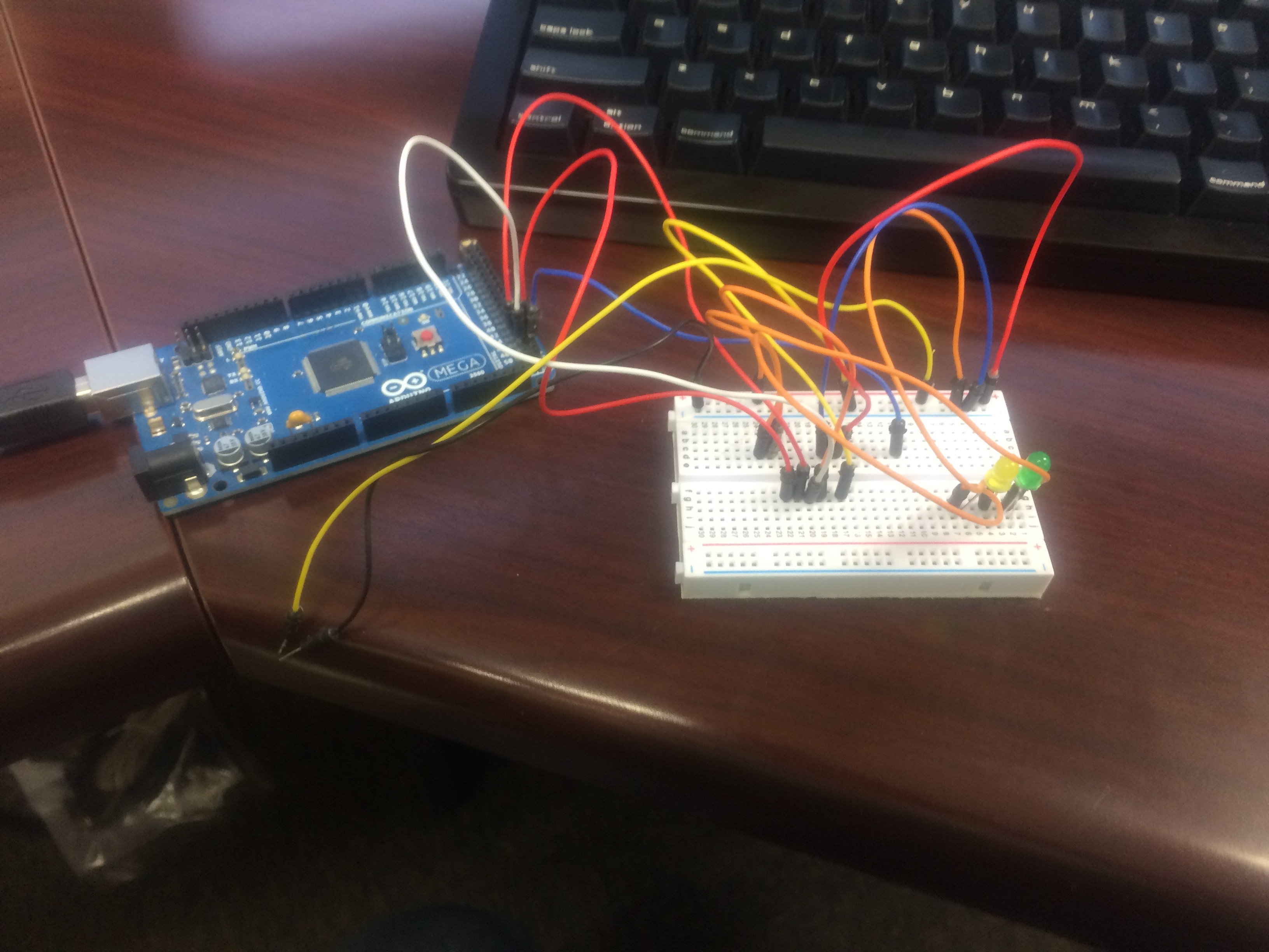
I know the wiring looks scary but it is actually very simple, here is the layout of the actual atmega chip:
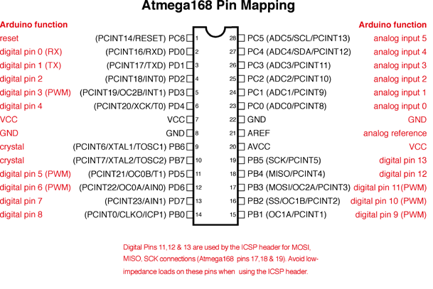
So the wiring goes like this:
Pin 1 – To Arduino Mega Pin 53
Pin 17 – To Arduino Mega Pin 51
Pin 18 – To Arduino Mega Pin 50
Pin 19 – To Arduino Mega Pin 52
Pin 7 – +5v
Pin 20 – +5v
Pin 8 – Ground
Pin 22 – Ground
Optional: Pin 13 to LED for status
For mega:
Also on the Arduino you need a .1uF capacitor, to prevent reset when the boot loader is uploaded I did this. That looks like this:
You will need a 0.1uF capacitor for the FTDI programming as well.
The last think you need to do is hook up your FTDI +5v and Ground to your breadboard rail, as there simply isn’t enough power supplied from the Arduino to run 2 Arduinos
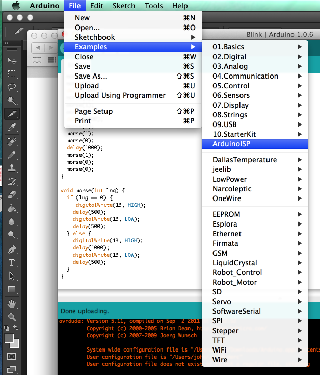
Now that you have done that you need to program your Arduino to Accept firmware (To be a ISP), First you need to upload the Example ArduinoISP:
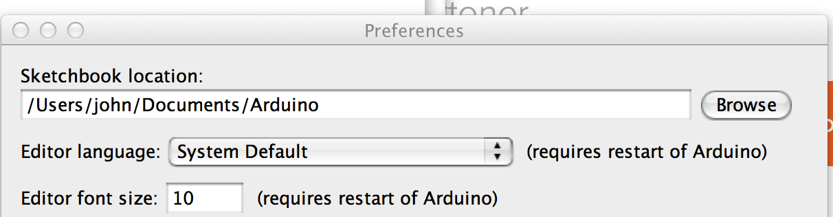
You must select your serial port etc, like normal, and upload the program. Now in the Arduino software go to Arduino > Preference, get your sketchbook location:
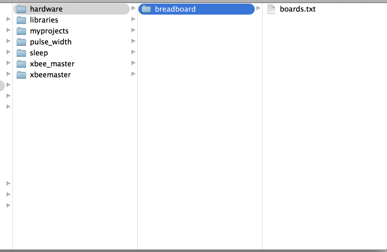
Now completely close the Arduino software, I have attached to this post the required, hardware file for Breadboarding Arduino, you must copy this into the hardware location of your sketchbook folder, like so:
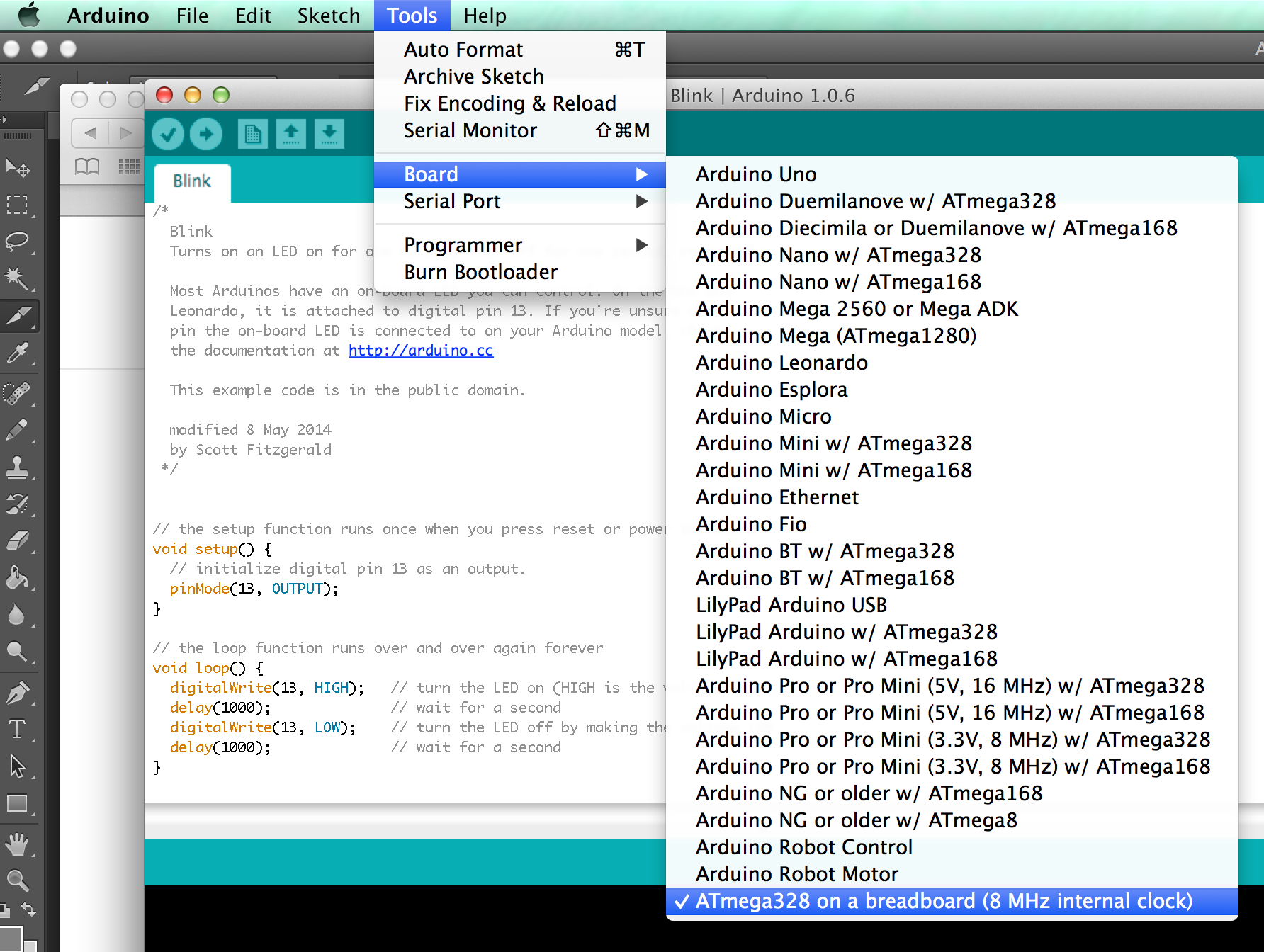
Ok you can now open up Arduino again. Notice the new board!
Now if you went the manly way of the PU chip, you need to edit your avrdude.conf, mine was located here, your mileage WILL very:
/Users/john/Downloads/Arduino.app/Contents/Resources/Java/hardware/tools/avr/etc/avrdude.conf
You need to find the section labeled: ATmega328P and change the signature make it look like this:
#signature = 0x1e 0x95 0x0F;
signature = 0x1e 0x95 0x14;
You will need both of these, so just comment them out the one for now and then add the other.
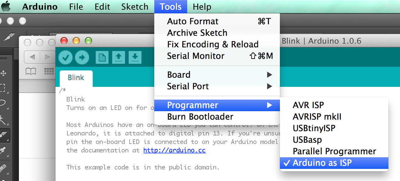
ok so now let’s burn this boot loader. Select the Serial port of the Arduino Mega, like normal. Change the programmer to Arduino as ISP:

You should see the light start flashing (if you hooked it up) it takes about 30 seconds to flash the chip. If you see an error about the signature, edit the avrdude.conf again, and switch the # in front of signatures around.
ok from there if you get no errors, you are flashed, and now running the Arduino boot loader.
Now comes the fun part running code.
You must connect the FTDI adapter.
So it goes like this:
Pin 1 -> 0.1uF capacitor -> DTR
Pin 2 -> TX
Pin 3 -> RX
Pin 7 -> +5v
Pin 8 -> GND
Pin 20 -> +5v
Pin 22 -> GND
For the blink application
Pin 19 -> LED +
now you can upload your Arduino software anytime you want.
–John “Think Tiny” Hass
boards